SBS4DCC - DCCSound USA - ESU
Pioneer Zephyr LokSound 5 Sound File
|
SBS4DCC, in cooperation with DCCSound USA, present the first-ever production of an ultra-realistic sound file for the Pioneer Zephyr.
This is the most accurate file available for the early Zephyrs and utilizes the power and performance of the ESU LokSound v4.0 and v4.0 Micro line of decoders.
Did we record a real Zephyr? No.
Those are long gone my friends. They have been relegated to Museum Duty so we improvised with the best information and recordings available today, 2015.
The file is the result of many hours of study of every source of media available for the prototype including movies, manuals and books.
The file is made possible only through the expertise and experience of DCC Sound USA in creating custom LokSound sound files.
The results of this effort are extremely satisfying and a sound you are sure to enjoy.
"All Aboard the Silver Streak!"
|
New in 2019
The
SBS4DCC - DCCSound USA - ESU Pioneer Zephyr LokSound 5 Sound File has been re-mastered from the original recordings to take full advantage of the Hi-Fi capabilities of the LokSound 5.
|
New in 2017
The SBS4DCC - DCCSound USA - ESU Pioneer Zephyr LokSound v4.0 Sound File now includes of the great Full-Throttle features found in the standard ESU sound file catalog.
|
Ordering a decoder with the Zephyr file is super simple.
Just locate the model of the ESU LokSound V4.0 decoder in the SBS4DCC storefront that you want to use and click the MORE INFO button to open the Item Details page.
Then enter the name or file number of the desired file (*NOTE* This is optional but helpful) and simply check the box next to the custom file option.
You will be charged a modest fee for some files that is automatically added to the item price.
Finally, click the ADD TO CART button and go through the checkout process like any other order.
|
The Pioneer Zephyr was built using the Winton 8 cylinder 201A prime mover.
Winton was purchased by EMC and the 8-201A eventually became the EMC 8-567.
The EMC engine evolved into the EMD 12-567 which powered the ubiquitous streamline-era E-units and the 16-567 which powered such models as the venerable GP and F-units.
Early Zephyr-type streamlined train sets that used the Winton 8-201A included:
Burlington Railroad
#9900 The Pioneer Zephyr
#9901 The Sam Houston Zephyr
#9902 The Ozark State Zephyr
*Note: The 9901/9902 were built as the original Twin Cities Zephyrs but were replaced quickly due to burgeoning demand for seat space.
#9903 The Mark Twain Zephyr
Boston & Maine - MainE Central
#6000 The Flying Yankee
Other applications for the engine include early Electro-Motive Corporation SC and SW model switchers. A custom sound file is available for these models as well.
12 and 16 cylinder variations of the Winton could be found in other early Streamliner experiments including the M10000 and its brethren, the Green Diamond, the ultra-sleek Rock Island TA's, as well as the EA's, E1's, 2's, and 3's.
There is a thorough analysis and history of the evolution from Winton to EMC in the last section of this page for those who are interested.
|
The prime mover for this sound file is built from recordings of a true 8-cylinder EMD 567 diesel, a rare recording in and of itself.
This is an important aspect of this sound file. You can substitute a 12 or 16-cylinder recording but the sound gets thicker, heavier and has more growl than the light bark of the 8-cylinder prototype.
The prime mover sequence has been modeled by DCC Sound USA to respond in a prototypical fashion as witnessed from the Burlington Zephyr's starring role in the 1934 cinematic classic, The Silver Streak.
The horn used for this file is a combination Leslie A-200 and A-125 based on the known configuration changes made to the Pioneer Zephyr shortly after it entered regular service as documented in the BRHS Burlington Bulletin. The Proto-N Pioneer Zephyr webpage is another good reference about the history of the horns on this train.
The bell has been modeled to simulate the speed and pitch of the Streak as witnessed in the movie.
Additional sound effects include doors opening and closing and air-conditioning compressor fans; a subtle but important sound effect given this was one of the first applications of air conditioning on the railroad and the Zephyrs windows did not open!
|
Full Throttle Sound File Function Map
|
A new version of the Zephyr file (coincidentally v4.0...) has been created and released in 2017 to incorporate the fantastic new ESU Full Throttle features. As a result we had to push the function map around a little to make it work.
|
F0 - Front / Rear Lights
F1 - Fast Bell
F2 - Leslie A125/A200 Airhorn
F3 - Doors Open / Close
F4 - Air Condition
F5 - Upper Dimmable Headlight
F6 - Upper Mars Headlight
F7 - Dynamic Brake
F8 - Prime Mover Startup/Shutdown
F9 - Drive Hold/Drivelock
F10 - Independent Brake
F11 - Dimmer
F12 - Brake Release
F13 - Compressor
F14 - Radiator Fan
F15 - Sanding Valve
F16 - Shift Mode (Disables the A125 Airhorn on F2)
F17 - Leslie A200 Airhorn
F18 - Leslie A125 Airhorn
|
Non-FT Sound File Function Map
|
F0 - Front/Rear HeadlightF1 - Fast Bell F2 - Leslie A125/A200 Airhorn F3 - Doors Open/Close F4 - Manual Nothing (Up) F5 - Upper Dimmable Headlight F6 - Upper MARS Headlight F7 - Air Conditioning Fans F8 - Manual Notching (Down) F9 - Prime Mover Startup/Shutdown F10 - Dimmer F11 - Braking Function F12 - Brake Set/Release F13 - Compressor F14 - Radiator Fan F15 - Sanding Valve F16 - Shift Mode (Disables the A125 Airhorn on F2) F17 - Leslie A200 Airhorn F18 - Leslie A125 Airhorn
|
Sound File Notes and Comments
|
A few notes about the file and settings... just so you know...
I am not able to program CVs with the decoder installed in the Con-Cor model. This is due to the design of the lighting circuit on the OEM board. I have to program the decoder on a test stand and the install in the model for verification.
The Default Address for the file is 3. The address should be programmed prior to installation if you wish to change this.
Analog Conversion, Railcom Bi-Directional Communication, non-DCC Protocols and the various Braking Section methods are turned off by default. Analog conversion is turned off by default to prevent "run-aways" in short-circuit situations. The other features are disabled because they are not needed by most users. It probably doesn't matter if they are on, but if I have a problem, I know THEY are off.
The motor tuning has been optimized for use with the Con-Cor model. I recommend using the LokSound Auto-Tune procedure to fine tune these settings to your model.
The Acceleration (CV3) and Deceleration (CV4) rates have been adjusted to simulate the train handling characteristics of this new, lightweight streamliner. You may want to tweak these further as well.
The headlights are configured to work as well as can be expected using the Plug-N-Play NEM651 8-pin NMRA connector in the Con-Cor Zephyr model. As designed, all lights in the model, including the Lower Front and Rear headlights are always on. Activating F0 makes the lower headlights directional. The additional lighting functions on F5 and F6 can only be used with the Post-WWII version of the model.
The Dimmer Function on F10 only dims the Upper headlight due to the design of the OEM board. The functionality of the Forward and Reverse outputs is limited by the unusual OEM board design.
The Braking Function is retained for consistent application and use of this project with the brake feature of NCE systems. The actual Dynamic Brake sound file has been omitted.
We have leveraged the Function Logic capability of the ESU LokSound V4.0 decoder to allow the user to disable the A125 half of the dual chime horn by selecting F16. When F2 and F16 are on, only the A200 horn will play. Additionally, we have included the individual horns on F17 (A200) and F18 (A125).
The CVs and Function Mapping may need reprogrammed by the user to work appropriately with other models and installations.
|
About The Leslie Airhorns
|
I should note that all Leslie Airhorns's are not alike.
Most sound files on the market feature a Leslie A-200-156, the so-called "Blat" horn of the 30's, 40's and 50's.
According to the atsf.railfan.net website, the early Zephyrs used a model A-200-H which later became the A-200-233.
According to the LocomotiveHorns.info webpage, each model of Leslie came in a variety of sizes each having a unique frequency and tone.
We believe the A-200 horn we are using is the A-200-156. We will include the -233 if we can ever get a good sound sample from such a rare breed.
|
Sound Sample and Demonstration
|
About Third Party Sound Files
|
The file is built for use with the ESU LokSound v4.0 line of sound decoders. Sorry, it cannot be used with the Select or any of the earlier LokSound versions.
This is a custom file created by a third-party producer using completely original recordings so it is pay-per-use file. That means there is an additional fee required for the use of this file. The fee is added to the order at the time of purchase.
Why is there a fee? Because it cost the third party money to record and produce it.
The file is only available from SBS4DCC or DCC Sound USA and cannot be downloaded from the ESU website.
DCC Sound and DCC Sound USA have been offering custom files for ESU Loksound decoders for years, primarily based on Australian prototypes.
|
About The Author USAF Captain Phil Dunlop
|
The Zephyr file was authored and edited by USAF Captain Phil Dunlop, a bad-ass United States Air Force F111A fighter pilot, Vietnam war veteran, ESU file author (he literally wrote the manual for ESU...), and model railroader extraordinaire.
Captain Dunlop flew for the 429th Tac Fighter Squadron known as the Black Falcons.. Phil has over 2200 in the F111-A/F and flew 122 combat missions, 42 over Hanoi. He was stationed at Mtn Home AFB Idaho, Nellis AFB Nevada, RAAF Amberley (Australia), RAF Lakenheath, RAF Upper Heyford (UK), and finally Fort Hood, Texas. To quote Phil, "at 200 feet, F-111 gets down and dirty, and we didn't fxxx around".
We chatted a lot about life and politics and Phil is always good to give you an education on the topic of the day. Many of you have gotten instruction from Phil on one of the ESU chat groups too.
You might have guessed I am passionate about the Silver Streak. I don't even remember now how we connected to pursue this project. I suppose it was just meant to be...
Phil and I exchanged about a thousand emails to develop the file and have exchanged about a thousand more over the years to support this offering.
Phil, thank you for making the Zephyr sound file a reality. You are one of the good guys...
|
About the Zephyrs Interior Lighting
|
Lighting is a minor detail that really makes a big impact on the authenticity of a model.
While it is super cool looking and a real crowd-pleaser at shows, I do want to make note about the cool-white fluorescent style lighting used on the Con-Cor version of the Zephyr models and to provide some guidance for those upgrading one of the many other models of this ground-breaking train.
|
These images of the interior light fixtures installed in the Streak were taken as it sits today at MSI in Chicago. You can clearly see the fixtures use traditional incandescent bulbs. There is no evidence it was ever any different.
Additionally, according to the book The American Railway Passenger Car, fluorescent lighting was first introduced in 1938 on the New York Central, some five years after the construction of the Pioneer Zephyr. Therefore, the appropriate choice for the color of any interior lighting would be a warm-white or incandescent tone.
|
Evolution Of The Winton 201 - EMD 567 Diesel
|
THE EMD 567 SERIES TWO-CYCLE UNIFLOW ENGINE, AN INSPIRATION: PART 1
“The boys worked all night and hoped the engines would run all the next day. It was no fun but we learned fast and a new design study was soon underway at Winton. To mention the parts with which we had trouble in Chicago would take far too much time. Let it suffice to say that I do not remember any trouble with the dip stick.“
E.W. Kettering, Chief Engineer, EMD
Predecessor to the 567 Series: The Winton 201
It’s 1930, the Great Depression is deepening and gasoline prices are rising. The railroads, recent adopters of gasoline-electric powered railcars for local passenger service, are screaming: “Gas prices are going up!”
GM had just recently purchased the Electro-Motive Corporation, an early builder of gasoline-electric rail cars and the Winton Engine Corporation, builders of the engines that powered Electro-Motive’s rail cars. The new division of GM, Electro-Motive Division (EMD), was set to task building a new engine to run not on distillate or gasoline, but diesel.
Up to this point, Winton’s largest 4-cycle gasoline railroad engine made 400 horsepower from 1,184 cubic inches. Winton’s early solution to the problem of making more power with cheaper fuel was their 900HP distillate engine. The engine, plagued with problems, made 900 horsepower when it could be kept running. EMD realized that the future of railroad combustion engines was more power, LOTS more power. This would allow the combustion powered train to haul much more weight and take to the main lines.
To build a more powerful engine, General Motors Research concluded the solution was a compression-ignition 2-cycle uniflow engine burning cheaper diesel fuel. This engine would use Winton’s recently developed (but far from perfected) unit injector. The 2-cycle engine, by it’s very nature, allows a higher volume-specific power output than a 4-cycle engine because it fires every revolution of the crankshaft, rather than every other revolution. A course of research and development began with the construction of several single-cylinder test engines. As problems were solved in the test engine, an 8-cylinder inline engine began to take shape, soon to be called the Winton 8-201.
“..I do not remember any trouble with the dip stick.” Such was the story at the GM Building during the 1933 World’s Fair. A pair of new engines of unconventional design, just recently assembled and still relatively untested, were on trial before the world.
Called the 8-201 because if their inline 8-cylinder configuration with a displacement of 201 cubic inches per cylinder, they would be discovered at the World’s Fair by Ralph Budd, president of the Chicago, Baltimore and Quincy Railroad. The 8-201, redesigned immediately after the World’s fair and designated the 8-201A, would power his groundbreaking new train, the Pioneer Zephyr. “Dieselization” of America’s railroads had begun.
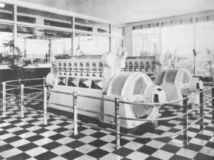
The Winton 8-201’s at the 1933 World’s Fair.
The Winton engines were unique in many respects. Beyond their novel fabrication almost entirely from welded steel plate, “powerpack” construction and unit injectors, they were one of the first uses of the poppet valve uniflow scavenged 2-stroke cycle.

The Winton Engine Corporation unitized injector, U.S. Patent 1,864,860. Filed Feb 11, 1931

Winton fabricated engine construction, U.S. Patent 1836,189. Filed Feb 14, 1930
One of the major issues to be solved in developing the 201 engine involved cooling the piston crown and ring belt. Winton’s solution to this problem is instructive as it is a problem I expect to face as well.

An early Winton 201 series piston. Not the large number of compression rings, heavy wall crown and ring belt. Also note the even temperature distribution between the crown and ring belt. lllustration Credit: “History and Development of the 567 Series General Motors Locomotive Engine” Page 11.
Initial development in the single-cylinder test engine concluded that conventional piston design was not appropriate. As power approached 82 1/2 HP per cylinder, the piston rings began sticking, presumably due to oil coking. Piston seizure soon followed after about 100 hours of operation. It was discovered that increasing the cooling oil flow to the piston crown did not necessarily reduce ring belt temperatures and that the piston shed almost 70% of it’s waste heat to the cylinder liner through the top ring. EMD’s solution to the problem was the heat dam piston.

A revised Winton 201 piston design. Note the much lighter construction, higher crown temperature and lower ring belt temperature. Illustration credit: “History and Development of the 567 Series General Motors Locomotive Engine” Page 13
The heat dam piston reduces the ability of the crown to transfer heat to the ring belt by limiting the area of metal connecting the two surfaces. This substantially reduced the ring belt temperature, but increased the crown temperature. A material change to cast iron was made at that time, presumably for it’s lower thermal conductivity and it’s capacity to resist the higher temperatures in the crown area. Piston cooling oil was used to cool the underside of the piston crown.
While the 201 and 201A series engines were variously plagued with problems related to piston cooling, crankcase stiffness and coolant leaks, the lessons learned from the Winton 8-201 and it’s larger cousins the 12-201 and 16-201 would directly produce the engine that finished “Dieselizing” the railroads of the world. It’s an engine which can still be heard running the iron today: The EMD 567 series. It is this engine that first introduced me to the 2-cycle uniflow design.
“…although we could talk a little two-cycle design, we spoke with a very heavy four-cycle accent. We did believe we could understand what a two-cycle engine was trying to tell us, so with the optimism of youth we barged into the design that ultimately turned out to be the 567.“
E.W. Kettering, Chief Engineer, EMD
The 567 Series Engine
In the mid 1930’s, EMD realized that the Winton 201 Series engine was not going to be sufficient to meet railroad demands as it wasn’t powerful or reliable enough. They discovered that fixing the problems of the 201 would require an entirely new engine and thus they decided to start with a clean sheet of paper. On one side they listed everything they got right with the 201. On the other side they listed all the failures. Their plan was deceptively simple: Fix the failures, keep what they got right and build a more powerful engine that would better use the space within the carbody of a locomotive.
Unlike the 201, an early emphasis was placed on design for manufacturability to increase interchangeablity, tooling commonality and productivity. As an example, all 567 engines use the same oil pump design. The only difference is the length of the gear teeth. An unintended benefit of this emphasis on interchangeability is that almost all parts of the engine, including revised designs, are interchangeable between engine serial numbers.
As with the 8-201, research began with a test engine studying cylinder liners, porting and pistons. The pistons required substantial development to further refine the crown cooling system begun with the 201. EMD found that traditional asymmetrical pistons with the pin bore though the wall of the piston caused substantial heat-induced stresses. These stresses resulted in ring belt cracking due to the temperature gradient between the crown and ring belt.

EMD’s first 2-567 test engine. Illustration Credit: “History and Development of the 567 Series General Motors Locomotive Engine” Page 18
Their solution to the temperature gradient problem was the “trunnion piston”. The piston pin is installed though a trunnion, which is in turn a slip fit in the piston crown. The trunnion is secured to the bottom of the piston by a snap ring. This elegant solution solved not only the ring belt cracking problem by reducing the temperature gradient across the piston, but also allows the whole piston to rotate, potentially distributing skirt and ring wear more evenly.
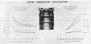
Winton and early EMD pistons suffered greatly from ring sticking due to high ring belt temperatures. This was solved by the EMD “heat dam” piston but presented a new challenge: The high temperature gradient caused the ring belt to separate from the piston crown. Illustration Credit: “History and Development of the 567 Series General Motors Locomotive Engine” Page 25.
Another discovery during development of the 567 Series worth noting is that, like many two-cycle engines, the 201 series suffered piston and liner scuffing around the cylinder ports. This can sometimes be due to the reduced contact area between the liner and the piston rings, resulting in metal to metal contact, ring breakage and eventual failure of the liner in the port strut contact area.
However, during testing of a 567 Series engine it was discovered that the cylinder liner operates at a much lower temperature around the intake ports. This naturally causes a straight-bored cylinder to contract in the area of the intake ports, in the same way tightening your belt constricts your gut!
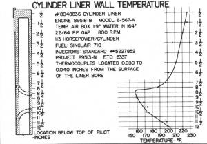
This illustration, taken from “History and Development of the 567 Series General Motors Locomotive Engine” shows the temperature gradient across the cylinder liner in the area of the intake ports. Illustration Credit: “History and Development of the 567 Series General Motors Locomotive Engine” Page 37
EMD’s solution? Rather than bore a taper in the cylinder, as is commonly done on air-cooled aircraft engines, they decided to relieve the port area about .014″ on diameter. This solved the piston and liner scuffing problem.

An illustration from the EMD 645 series Engine Maintenance Manual, showing a cross-section of the liner and the location of liner diametral relief.
Numerous other improvements in injectors, crankcase structure, rod and rod bearing design, exhaust valves and valve bridges and other components resulted in what became the 567 Series. At 567 cubic inches displacement per cylinder and a rated power of 1,750 HP in the later models at a piston speed of 2,100 FPM, the 567 is the engine that “Dieselized” American railroads.
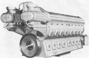
An early 567 Series engine, note the square hand hole covers. Later 567’s and modern EMD engines have round hand hole covers. Illustration Credit: “History and Development of the 567 Series General Motors Locomotive Engine” Page 64
While railroad history isn’t the purpose of this blog, it’s worth noting the enormous effect EMD’s engines have had on American railroad operations. The 567 Series was installed in the EMD “E Series”, “FT Series” and the exceptionally popular “GP Series” locomotives, among others.
While the GP locomotives are by far the most popular, it’s an almost forgotten FT unit, GM-103, that is the most historically important. Powered by four 1,350HP 567A engines, it was an EMD mainline freight demonstrator. Freight, not passengers, are the bread and butter of American railroads and it was FT-103 that sold some American railroads completely on the diesel and forced the rest to follow.

Half of GM FT-103 repainted in it’s orginal demonstrator colors at the 1989 EMD open house in LaGrange, IL. Photo Credit: Unknown

AT&SF #115, a complete four-unit GM FT. Photo Credit: Jack Delano / Wikipedia
Dick Dilworth, Chief Engineer of EMD at the time, tells it best. After hearing that a railroad executive, undoubtedly William Jeffers of the Union Pacific Railroad, had talked down to one of EMD’s salesmen about the capability of their FT-103, he got on the phone:
“I hear you’ve been taking advantage of one of our men. I’d like to make a prediction. If you’ll put our four-unit freight locomotive alongside your Big Boy on that hill out in Utah, we’ll push your Big Boy so far back into Lionel’s window with the rest of the toys that no one will ever talk about it again.”
Today, EMD locomotives powered by the same basic engine architecture pioneered in the 1930’s pull heavier trains than five UP Big Boys ever could over “that hill” (The Wasatch Grade).
FT-103 now resides under cover at the Museum of Transportation in St. Louis, MO alongside many of the steam locomotives it helped push back into Lionel’s window. The technology it brought to the railroad lives on and relatively unchanged from it’s original form.
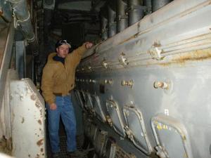
Me in the head unit of FT-103 with it’s 567A engine.
If you’ve made it this far you’re no doubt thinking “This man’s fallen off his rocker!” “A locomotive engine design for a motorcycle!?!” That’s not really the case, although it was the EMD engine and their prolific use on local short line railroads that introduced me to the concept of the uniflow engine.
To understand why the EMD engine is inspiring I should backtrack a little and explain a bit about the two-cycle engine, the history of motorcycle racing and what makes the uniflow engine the right choice for the Paulding Racer.
The Two Cycle Engine
It is the two-cycle engine design, not the four-cycle, which has produced the largest array of displacements, service types and power levels. One of the smallest two-cycle engines produced is the loop scavenged Cox .049 cubic inch “Babe Bee”, a control line model airplane engine fueled by nitromethane. On the other end of the scale is Wartsila-Sulzer’s uniflow RTA-96, a direct-drive uniflow marine diesel engine displacing over 111,000 cubic inches per cylinder.

Cover art for the Wartsila RT-FLEX96C and RTA96C Technology Review brochure showing bedding of the crankshaft. The man on the left should provide sufficient scale.
According to Cyril Lovesey, Sir Stanley Hooker once poked fun at the four-stroke engine, stating that it uses “one stroke to produce power and three to wear it out.” While the four-stroke engine can devote one full stroke of the piston (half a crankshaft revolution) to each of the four portions of a combustion cycle, the two-stroke engine must do everything in only one full revolution. The four portions of a complete combustion cycle in the four-stroke engine are:
1) Intake: The camshaft operated intake valve opens and the piston moves towards bottom of the cylinder, sucking in a fresh air and fuel charge.
2) Compression: All valves are closed and the mixture is compressed prior to ignition.
3) Power: With all the valves remaining close, the fuel mixture is ignited and expanded. Power derived from the expansion is transmitted to the crankshaft.
4) Exhaust: The exhaust valve opens and the spent combustion gasses are forced from the cylinder in preparation for a fresh charge.
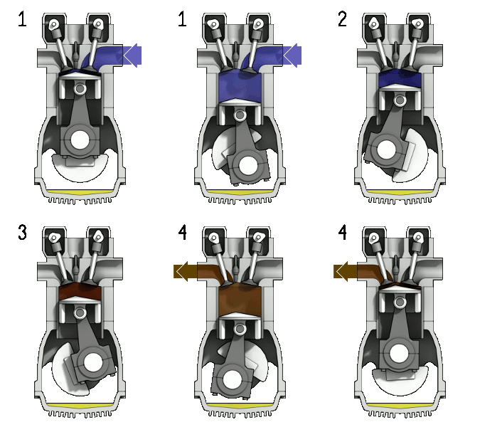
The four strokes of a four-stroke engine. Animation Credit: Wikipedia user Zephyris
On the other hand, the two-stroke engine has only one crankshaft revolution to complete everything the four-stroke engine does in two revolutions. This is accomplished by combining the intake of a fresh fuel and air charge with expelling the exhaust gasses from the cylinder. This operation is calledscavenging.
The animation below is of a loop-scavenged two-stroke reed valve engine using the crankcase as an induction air compressor and is typical of chainsaw, weed trimmer and dirt bike engines. The lubrication system is the total loss type, depending on oil inducted into the engine through the carburetor to lubricate the engine internals.
The cycle begins when the piston rises in the compression stroke. Atmospheric air (blue) is drawn though the carburetor where it picks up a combustible mixture of fuel and lubricating oil (green). The mixture passes though the reed valves into the crankcase. As the piston reaches Top Dead Center (TDC) the reeds close and the piston begins moving down, reducing the volume of the crankcase and compressing the mixture slightly.
As the piston continues downward, it uncovers the exhaust port (known as the release point of the cycle), then the intake port. The mixture compressed in the crankcase is forced though the transfer ports into the cylinder. Some of it escapes out the open exhaust port.
As the piston rises in the next compression stroke the intake port is blocked off by the advancing piston. At the same time, an exhaust pulse traveling down the tuned expansion chamber pushes the majority of the fresh mixture back into the cylinder, but only if the engine is operating within the range of the tuned exhaust. If the engine is operating outside the range of the tuned exhust that portion of the mixture is lost, contributing to poor volumetric efficiency.
This piston continues advancing to the trapping point (the point at which the exhaust port is blocked off by the piston.) Mixture compression occurs followed by ignition and expansion. As the piston is forced downwards past the release point again, an exhaust pulse begins traveling down the tuned exhaust pipe and the cycle starts again
The Uniflow Engine
At this point, the more motorcycle-oriented of you are saying “The two-cycle bike is a peaky wheelie monster and unsuitable for modern road racing unless you want to get killed. Besides, today’s 4-cycle bikes are more powerful than the old 2-smokes ever were and are better at helping the rider get that power to the road where it counts for something!”
That is true of port scavenged engines, yes. However, it is not the case with the uniflow engine as evidenced by the fact that it’s an excellent choice for moving the heaviest loads ever moved by an internal combustion engine. The same things that make an engine suitable for pulling a freight train or driving a ship make the perfect engine for a cutting edge road racing motorcycle. Namely, a broad and flat torque curve and copious, predictable power.
By negating the need for a organ pipe tuned exhaust and through the use of forced induction, the uniflow engine can have the throttle characteristics of a 4-cycle engine. In addition, it can produce more power than a four-cycle engine from the same displacement as a two-cycle engine fires twice as often. This can place less stress on many of the rotating components of the engine and produces a smoother power response.
Operating Principle of the Uniflow Engine
Unlike a reed valve engine, the uniflow engines require a scavenge blower to “breathe” as it does not use the crankcase to compress the mixture before transferring it to the cylinder. The scavenge blower can be an engine-driven supercharger such as a Roots Blower, a centrifugal supercharger, or even a turbocharger which is powered by the engine at low throttle settings to provide starting air. The uniflow engine is so named because gas passes in only one direction though the engine, as seen below.

Illustration from the EMD 567 Engine Maintenance Manual illustrating the scavenging and compression events.
The start of the cycle begins at position A, with the piston at bottom dead center. Scavenging air provided under pressure by the roots blower enters the cylinder ports uncovered by the piston and forces the spent fuel gasses up the cylinder and through the exhaust valve s.
As the crankshaft advances at position B, the piston ports are closed by the piston (trapping point) and compression begins.
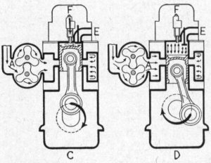
Illustration from the EMD 567 Engine Maintenance Manual illustrating the injection and expansion events.
As the piston reaches top dead center, as in position C, fuel injection occurs and combustion takes place. The piston is forced downwards to position D. As the cylinder pressure falls and before the intake ports are uncovered again, the exhaust valves open and begin venting the remaining exhaust gasses to prevent blowback into the induction air belt.
** This article has been copied From The Paulding Racer Blog
|
|
|